Select Question Set:
Unlock IMPORTANT QUESTION
This question was bookmarked by 5 NEET 2025 toppers during their NEETprep journey. Get Target Batch to see this question.
✨ Perfect for quick revision & accuracy boost
Buy Target Batch
Access all premium questions instantly
The circuit shown in figure is given an input signal \(V_i,\) which varies with time and the corresponding output is \(V_o.\) Then,

1.
\(V_o=V_i+E\)
2.
\(V_o=V_i-E\)
3.
\(V_o=V_i,\) only when \(V_i>E\)
4.
\(V_o=V_i,\) only when \(V_i<E\)
Subtopic: PN junction |
Level 3: 35%-60%
Hints
Under what conditions will diode \(D_1\) conduct?

1. \(V_A>V_B+V_0\)
2. \(V_A<V_B+V_0\)
3. \(V_A>V_B-V_0\)
4. \(V_A<V_B-V_0\)

1. \(V_A>V_B+V_0\)
2. \(V_A<V_B+V_0\)
3. \(V_A>V_B-V_0\)
4. \(V_A<V_B-V_0\)
Subtopic: PN junction |
65%
Level 2: 60%+
Hints
In the circuit shown in the adjacent diagram, \(D_1,D_2\) are ideal diodes and \(r\)'s are small resistances. Then:


| 1. | no current flows in the circuit |
| 2. | current flows anticlockwise |
| 3. | current flows clockwise |
| 4. | current only flows through \(D_2\) and not through \(D_1\) |
Subtopic: Applications of PN junction |
66%
Level 2: 60%+
Hints
The current flowing through the diode \(D_2\) is:
 1. zero
2. \(4~\text{mA}\)
3. \(2.5~\text{mA}\)
4. \(0.8~\text{A}\)
 1. zero
2. \(4~\text{mA}\)
3. \(2.5~\text{mA}\)
4. \(0.8~\text{A}\)
Subtopic: Applications of PN junction |
68%
Level 2: 60%+
Hints
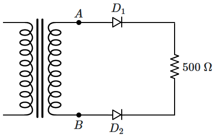
\(D_1,D_2\) are ideal diodes and the output \((V_{AB})\) of the transformer is \(10\) V (RMS). The current through the resistor is:
 1. zero
2. \(20\) mA
3. \(40\) mA
4. \(20\sqrt2\) mA
 1. zero
2. \(20\) mA
3. \(40\) mA
4. \(20\sqrt2\) mA
Subtopic: Applications of PN junction |
Level 3: 35%-60%
Hints
What does the following logic circuit represent?


| 1. | AND | 2. | OR |
| 3. | NOR | 4. | XOR |
Subtopic: Logic gates |
69%
Level 2: 60%+
Hints

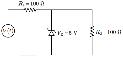
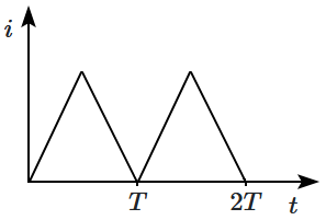
For the above circuit, the applied voltage \(V(t)\) is periodic and linear, and is shown by the waveform below:

The current flowing through \(R_2\) varies as:
| 1. |  |
2. |  |
| 3. |  |
4. |  |
Subtopic: PN junction |
57%
Level 3: 35%-60%
Hints
If an AND-gate and an OR-gate are OR-ed together, the resulting gate is:
1. AND
2. OR
3. XOR
4. none of the above
1. AND
2. OR
3. XOR
4. none of the above
Subtopic: Logic gates |
Level 3: 35%-60%
Hints
The system of gates shown in the adjacent diagram represents

1. AND gate
2. OR gate
3. XOR gate
4. null gate (always zero)

1. AND gate
2. OR gate
3. XOR gate
4. null gate (always zero)
Subtopic: Logic gates |
72%
Level 2: 60%+
Hints
The input to a Zener diode circuit is an AC-voltage along with a DC: \(V_i=(20~\text V)\sin\omega t+(20~\text V)~\)
Current flows through the diode:

Current flows through the diode:

| 1. | continuously, in both directions |
| 2. | continuously, only in one direction |
| 3. | intermittently, in both directions |
| 4. | intermittently, only in one direction |
Subtopic: Applications of PN junction |
Level 3: 35%-60%
Hints
Select Question Set:


