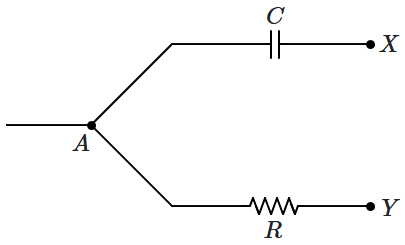
An AC-voltage is applied across the ends \(A,B\) of the circuit shown in the figure, the RMS voltage being \(V_0\). It is observed that the RMS currents in all the three branches are equal to \(\dfrac{V_0}{R}\). The total current entering at \(A\) equals:

| 1. | \(\dfrac{V_0}{R}\) | 2. | \(\sqrt{2}\dfrac{V_0}{R}\) |
| 3. | \(\Big(\sqrt{2}+1\Big)\dfrac{V_0}{R}\) | 4. | \(\sqrt{3}\dfrac{V_0}{R}\) |
The charge flowing through a resistance \(R\) is given by,
\(q = A\sin\omega t+B\cos\omega t\)
The heat produced in the resistance over a very long time \(\Delta t\) (much greater than \(T = 2\pi/ \omega\)) is:
| 1. | \(\omega^{2}\left(A^{2}+B^{2}\right) R \Delta t\) | 2. | \(\omega^{2}\left(A^{2}-B^{2}\right) R \Delta t\) |
| 3. | \(\dfrac{1}{2} \omega^{2}\left(A^{2}+B^{2}\right) R \Delta t\) | 4. | \(\dfrac{1}{2} \omega^{2}\left(A^{2}-B^{2}\right) R \Delta t\) |
An inductor \(200\text{ mH}, \) capacitor \(20~\mu\text{F}\) and a resistance of \(200~\Omega\) are connected in series across a source of EMF, \(E = (20~\text{V})\sin(500t) \), where \(t\) is in second. The power loss in the circuit is:
1. \(2~\text{W}\)
2. \(1~\text{W}\)
3. \(0.5~\text{W}\)
4. \(0.25~\text{W}\)
\(e=V_0\sin(wt)\)
and the current, \(i\) is
\(i=I_0\cos(wt-\phi).\) The average power dissipated per cycle is:
| 1. | \(V_{0} I_{0} {\cos\phi}\) |
| 2. | \(\dfrac{V_{0} I_{0} \cos \phi}{2}\) |
| 3. | \(V_{0} I_{0} \sin \phi\) |
| 4. | \(\dfrac{V_{0} I_{0} \sin \phi}{2}\) |
1. \(0.4~\text{A}\)
2. \(0.8~\text{A}\)
3. \(6.4~\text{A}\)
4. \(12.8~\text{A}\)

| 1. | zero | 2. | \(\sqrt 2 V_r \) |
| 3. | \(2 V_r\) | 4. | \(\dfrac{V_r}{\sqrt 2}\) |

| 1. | \(\dfrac{V_r}{3}\) | 2. | \(\dfrac{2V_r}{3}\) |
| 3. | \(\dfrac{V_r}{2}\) | 4. | \(V_r\) |
In the given scenario, the voltage, \(V_2 > V_1,\) and no current flow through the source on the left. The phase difference between the two sources is \(\phi.\)

Which of the following expressions correctly relates \(\phi\text{?}\)
| 1. | \(R\sin\phi= \dfrac{1}{\omega C}\) | 2. | \(R\cos\phi= \dfrac{1}{\omega C}\) |
| 3. | \(R\tan\phi= \dfrac{1}{\omega C}\) | 4. | \(R\cot\phi= \dfrac{1}{\omega C}\) |

1. \(V_o = V_m\)
2. \(V_o < V_m \)
3. \(V_o > V_m\)
4. any of the above can be possible.

1. \(0.2~\text{A}\)
2. \(0.15~\text{A}\)
3. \(0.45~\text{A}\)
4. \(0.9~\text{A}\)


