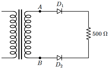
The current flowing through the diode \(D_2\) is:
 1. zero
2. \(4~\text{mA}\)
3. \(2.5~\text{mA}\)
4. \(0.8~\text{A}\)

To unlock all the explanations of this course, you need to be enrolled.

To unlock all the explanations of this course, you need to be enrolled.
 1. zero
2. \(20\) mA
3. \(40\) mA
4. \(20\sqrt2\) mA

To unlock all the explanations of this course, you need to be enrolled.

To unlock all the explanations of this course, you need to be enrolled.

| 1. | AND | 2. | OR |
| 3. | NOR | 4. | XOR |

To unlock all the explanations of this course, you need to be enrolled.

To unlock all the explanations of this course, you need to be enrolled.

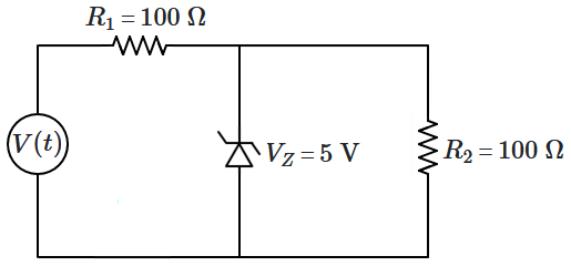
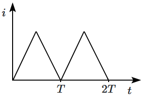
For the above circuit, the applied voltage \(V(t)\) is periodic and linear, and is shown by the waveform below:

The current flowing through \(R_2\) varies as:
| 1. |  |
2. |  |
| 3. |  |
4. |  |

To unlock all the explanations of this course, you need to be enrolled.

To unlock all the explanations of this course, you need to be enrolled.
1. AND
2. OR
3. XOR
4. none of the above

To unlock all the explanations of this course, you need to be enrolled.

To unlock all the explanations of this course, you need to be enrolled.

1. AND gate
2. OR gate
3. XOR gate
4. null gate (always zero)

To unlock all the explanations of this course, you need to be enrolled.

To unlock all the explanations of this course, you need to be enrolled.
Current flows through the diode:

| 1. | continuously, in both directions |
| 2. | continuously, only in one direction |
| 3. | intermittently, in both directions |
| 4. | intermittently, only in one direction |

To unlock all the explanations of this course, you need to be enrolled.

To unlock all the explanations of this course, you need to be enrolled.

| 1. | \(i=0.05\) A if \(V_{AB}\geq10\) V and \(i=\dfrac{V_{AB}}{200~\Omega}\) otherwise |
| 2. | \(i=0.05\) A if \(V_{AB}\leq10\) V and \(i=\dfrac{V_{AB}}{200~\Omega}\) otherwise |
| 3. | \(i=0.05\) A |
| 4. | \(i=\dfrac{V_{AB}}{200~\Omega}\) |

To unlock all the explanations of this course, you need to be enrolled.

To unlock all the explanations of this course, you need to be enrolled.

1. \(B\) AND \(C\)
2. \(B\) OR \(C\)
3. \(B\)
4. \(C\)

To unlock all the explanations of this course, you need to be enrolled.

To unlock all the explanations of this course, you need to be enrolled.

| 1. | only \(D_3\) | 2. | \(D_1\) and \(D_3\) |
| 3. | all of the diodes | 4. | none of the diodes |

To unlock all the explanations of this course, you need to be enrolled.

To unlock all the explanations of this course, you need to be enrolled.


