
 Q. No.
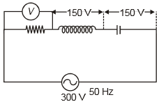
In the given circuit the reading of voltmeter are 300V each. The reading to the voltmeter and ammeter A are respectively :

(a) 150V, 2.2A
(b) 220V, 2.2A
(c) 220V, 2.0A
(d) 100V, 2.0A
दिए गए परिपथ में, वोल्टमीटर प्रत्येक का पाठ्यांक 300V हैं। वोल्टमीटर और एमीटर के पाठ्यांक क्रमशः हैं:
(a) 150V, 2.2A
(b) 220V, 2.2A
(c) 220V, 2.0A
(d) 100V, 2.0A


In a series LCR circuit, resistance R = 10Ω and the impedance Z = 20Ω. The phase difference between the current and the voltage is
(1) 30°
(2) 45°
(3) 60°
(4) 90°
एक श्रेणी LCR परिपथ में, प्रतिरोध R = 10Ω और प्रतिबाधा Z = 20Ω है। धारा और वोल्टता के बीच कलांतर है:
(1) 30°
(2) 45°
(3) 60°
(4) 90°
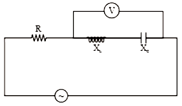
In the circuit given below, the reading of the voltmeter V will be

1. 0
2. 100 V
3. 200 V
4. 300 V
नीचे दिए गए परिपथ में, वोल्ट्मीटर V का पाठ्यांक होगा
1. 0
2. 100V
3. 200V
4. 300V


If \(\begin{array}{ccc}{\mathrm{X_{L}}}&{=}&{\mathrm{X_{C}}}\end{array}\) then the reading of ideal voltmeter is :
1. \(\begin{array}{ccccc}\mathrm{V}&=&\mathrm{V}_\mathrm{L}&\cdot&\mathrm{V}_\mathrm{C}\end{array}\)
2. \(\mathrm{V}=\sqrt{V_{\mathrm{R}}^{2}+V_{\mathrm{L}}^{2}}\)
3. \(\begin{array}{rcl}\mathrm{V}&=&\sqrt{\mathrm{V}_{\mathrm{R}}^{2}\quad+\quad\mathrm{V}_{\mathrm{L}}\quad-\quad\mathrm{V}_{\mathrm{C}}^{2}}\end{array}\)
4. zero
यदि \(\begin{array}{ccc}{\mathrm{X_{L}}}&{=}&{\mathrm{X_{C}}}\end{array}\) है, तब आदर्श वोल्टमीटर का पाठ्यांक है:

1. \(\begin{array}{ccccc}\mathrm{V}&=&\mathrm{V}_\mathrm{L}&\cdot&\mathrm{V}_\mathrm{C}\end{array}\)
2. \(\mathrm{V}=\sqrt{V_{\mathrm{R}}^{2}+V_{\mathrm{L}}^{2}}\)
3. \(\begin{array}{rcl}\mathrm{V}&=&\sqrt{\mathrm{V}_{\mathrm{R}}^{2}\quad+\quad\mathrm{V}_{\mathrm{L}}\quad-\quad\mathrm{V}_{\mathrm{C}}^{2}}\end{array}\)
4. शून्य
The diagram shows a capacitor C and a resistor R connected in series to an ac source. V1 and V2 are voltmeters and A is an ammeter:

Consider now the following statements
I. Readings in A and V2 are always in phase
II. Reading in V1 is ahead in phase with reading in V2
III. Readings in A and V1 are always in phase
Which of these statements is/are correct?
(1) I only
(2) II only
(3) I and II only
(4) II and III only
आरेख में एक संधारित्र C और प्रतिरोध R, ac स्त्रोत के साथ श्रेणीक्रम में जुड़े हुए दर्शाए गए है। V1 और V2 वोल्टमीटर हैं और A ऐमीटर है:
अब निम्नलिखित कथनों पर विचार कीजिए -
I. A और V2 में पाठ्यांक सदैव कला में हैं।
II. V1 में पाठ्यांक, V2 के पाठ्यांक से कला में आगे है।
III. A और V1 में पाठ्यांक सदैव कला में हैं।
निम्न में से कौन-सा कथन सही है/हैं?
(1) केवल I
(2) केवल II
(3) केवल I और II
(4) केवल II और III
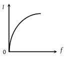
An ac source of variable frequency f is connected to an LCR series circuit. Which one of the graphs in the figure represents the variation of the current I in the circuit with frequency f :
(1)

(2)
(3)

(4)

एक परिवर्ती आवृत्ति f का एक प्रत्यावर्ती स्रोत श्रेणी LCR परिपथ से जुड़ा हुआ है। आकृति में कौन सा आलेख आवृत्ति f के साथ परिपथ में धारा I के परिवर्तन को दर्शाता है:
(1)
(2)
(3)
(4)


A constant voltage at different frequencies is applied across a capacitance C as shown in the figure. Which of the following graphs

Correctly depicts the variation of current with frequency?
(1)

(2)

(3)

(4)

विभिन्न आवृत्तियों पर एक नियत वोल्टता एक संधारित्र C के सिरों पर लागू की जाती है जैसा कि चित्र में दर्शाया गया है। निम्नलिखित में से कौन सा ग्राफ सही तरह से आवृत्ति के साथ धारा के परिवर्तन को दर्शाता है?
*Signal generator - एकल जनित्र
(1)
(2)
(3)
(4)
A resistance 'R' draws power 'P' when connected to an AC source. If an inductance is now placed in series with the resistance, such that the impedance of the circuit becomes 'Z' the power drawn will be:
एक प्रतिरोध 'R', शक्ति 'P' को निर्गत करता है जब यह AC स्रोत से जुड़ा है। यदि एक प्रतिघात को अब प्रतिरोध के साथ श्रेणीक्रम में इस प्रकार रखा जाता है कि परिपथ की प्रतिबाधा 'Z' हो जाती है, तब निर्गत शक्ति होगी:
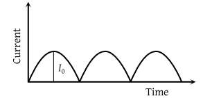
The output current versus time curve of a rectifier is shown in the figure. The average value of output current in this case is
(1) 0
(2)
(3)
(4) I0
एक दिष्टकारी के निर्गत धारा बनाम समय वक्र को चित्र में दिखाया गया है। इस स्थिति में निर्गत धारा का औसत मान है:
*current - धारा
*time - समय
(1) 0
(2)
(3)
(4) I0


A series R-C circuit is connected to an alternating voltage source. Consider two situations:
1. When the capacitor is air-filled.
2. When the capacitor is mica filled.
Current through the resistor is I and voltage across the capacitor is V then
(a)Va<Vb
(b)Va>Vb
(c)ia>ib
(d)Va=Vb
एक श्रेणी R-C परिपथ को एक प्रत्यावर्ती वोल्टेज स्रोत से जोड़ा गया है। दो स्थितियों पर विचार कीजिए:
1. जब संधारित्र हवा से भरा होता है।
2. जब संधारित्र अभ्रक भरा होता है।
प्रतिरोध के माध्यम से धारा I और संधारित्र के सिरों पर वोल्टेज V है
(a) Va<Vb
(b) Va>Vb
(c) ia>ib
(d) Va=Vb
© 2025 GoodEd Technologies Pvt. Ltd.