
 Q. No.
A sinusoidal voltage of peak value 283 V (suppose the frequency of the source can be varied) is applied to a series LCR circuit in which R = 3, L = 25.48 mH, and C = 796 µF. The frequency of the source at which resonance occurs is:
1. 35.4 Hz
2. 50 Hz
3. 60 Hz
4. 39.7 Hz


A sinusoidal voltage of peak value \(283~\text{V}\) (assume that the frequency of the source can be varied) is applied to a series \(LCR\) circuit in which \(R=3~\Omega\), \(L=25.48~\text{mH}\), and \(C= 796~\mu\text{F}\). The current in the circuit at the resonance is:
1. \(60~\text{A}\)
2. \(66.7~\text{A}\)
3. \(65~\text{A}\)
4. \(63.3~\text{A}\)
A sinusoidal voltage of peak value \(283~\text{V}\) (suppose the frequency of the source can be varied) is applied to a series LCR circuit in which \(R=3~\Omega\), \(L = 25.48~\text{mH}\), and \(C= 796~\mu\text{F}\). The power dissipated at the resonant condition is:
1. \(10.55~\text{kW}\)
2. \(11.17~\text{kW}\)
3. \(12.25~\text{kW}\)
4. \(13.35~\text{kW}\)


A sinusoidal voltage of peak value 283 V and frequency 50 Hz is applied to a series LCR circuit in which R = 3, L = 25.48 mH, and C = 796 µF. The power factor is:
1. 0.4
2. 0.5
3. 0.3
4. 0.6
A sinusoidal voltage of peak value 283 V and frequency 50 Hz is applied to a series LCR circuit in which R = 3, L = 25.48 mH, and C = 796 µF. The power dissipated in the circuit is:
1. 6000 W
2. 5200 W
3. 4800 W
4. 4500 W
A sinusoidal voltage of peak value 283 V and frequency 50 Hz is applied to a series LCR circuit in which R = 3, L = 25.48 mH, and C = 796 µF. The approximate phase difference between the voltage across the source and the current is:
A sinusoidal voltage of peak value 283 V and frequency 50 Hz is applied to a series LCR circuit in which R = 3, L = 25.48 mH, and C = 796 µF. The impedance of the circuit is:
1. 5
2. 8
3. 4
4. 2
Which one of the following is incorrect?
| 1. | For circuits used for transporting electric power, a low power factor implies large power loss in transmission. |
| 2. | Power factor can often be improved by the use of a capacitor of appropriate capacitance in the circuit. |
| 3. | For circuits used for transporting electric power, a low power factor implies low power loss in transmission. |
| 4. | Both (1) and (2) |
A resistor of \(200~\mathrm{\Omega}\) and a capacitor of \(15.0~\mu\text{F}\) are connected in series to a \(220~\text{V}\), \(50\) Hz AC source. The voltage (RMS) across the resistor and the capacitor are respectively:
1. \( 160.3 ~\text{V}, 160.3 ~\text{V} \)
2. \( 151 ~\text{V}, 151 ~\text{V} \)
3. \( 160.3 ~\text{V}, 151 ~\text{V} \)
4. \( 151 ~\text{V}, 160.3 ~\text{V}\)
A light bulb and an open coil inductor are connected to an ac source through a key as shown in the figure.
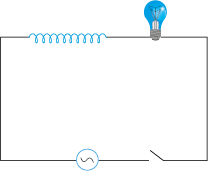
The switch is closed and after some time, an iron rod is inserted into the interior of the inductor. The glow of the light bulb:
1. increases
2. decreases
3. is unchanged, as the iron rod is inserted
4. first increases and then decreases
© 2024 GoodEd Technologies Pvt. Ltd.