A voltmeter has a resistance G and it can measure a maximum voltage of V. To convert it in a voltmeter of range nV, the value of resistance required is :
1. (n - 1)G in series
2. (n - 1)G in parallel
3. in parallel
4. in series
A current wire is hidden in a wall. Its position can be located with the help of a
1. Moving coil galvanometer
2. Voltmeter
3. Hotwire ammeter
4. Magnetic needle
The resistance of \(1~\text{A}\) ammeter is \(0.018~\Omega\). To convert it into \(10~\text{A}\) ammeter, the shunt resistance required will be:
1. \(0.18~\Omega\)
2. \(0.0018~\Omega\)
3. \(0.002~\Omega\)
4. \(0.12~\Omega\)
When a \(12~\Omega\) resistor is connected in parallel with a moving coil galvanometer, its deflection reduces from \(50\) divisions to \(10\) divisions. What will be the resistance of the galvanometer?
1. \(24~\Omega\)
2. \(36~\Omega\)
3. \(48~\Omega\)
4. \(60~\Omega\)
A galvanometer having a resistance of \(8~\Omega\) is shunted by a wire of resistance \(2~\Omega\). If the total current is \(1~\text{A}\), the part of it passing through the shunt will be:
1. \(0.25~\text{A}\)
2. \(0.8~\text{A}\)
3. \(0.2~\text{A}\)
4. \(0.5~\text{A}\)
In a moving coil galvanometer, the deflection of the coil is related to the electrical current i by the relation
1.
2.
3.
4.
A small coil of N turns has an effective area A and carries a current I. It is suspended in a horizontal magnetic field such that its plane is perpendicular to . The work done in rotating it by about the vertical axis is
1. 2.
3. 4.
Which among the following options needs to be decreased to increase the sensitivity of a moving coil galvanometer?
| 1. | the number of turns in the coil. | 2. | the area of the coil. |
| 3. | the magnetic field. | 4. | the couple per unit twist of the suspension. |
The field normal to the plane of a coil of n turns and radius r which carries a current i is measured on the axis of the coil at a small distance h from the centre of the coil. This is smaller than the field at the centre by the fraction
1.
2.
3.
4.
A coil having N turns is wound tightly in the form of a spiral with inner and outer radii a and b respectively. When a current I passes through the coil, the magnetic field at the centre is:
1. 2.
3. 4.
A current-carrying wire is placed in a uniform magnetic field in the shape of the curve \(y= \alpha \sin \left({\pi x \over L}\right),~0 \le x \le2L.\)
What will be the force acting on the wire?

| 1. | \(iBL \over \pi\) | 2. | \(iBL \pi\) |
| 3. | \(2iBL \) | 4. | zero |
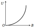
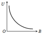
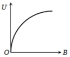
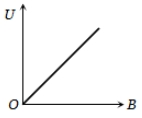
If induction of magnetic field at a point is B and energy density is U, then which of the following graphs is correct?
1. 
2. 
3. 
4. 
A particle of charge \(+q\) and mass \(m\) moving under the influence of a uniform electric field \(E\hat i\) and a uniform magnetic field \(\mathrm B\hat k\) follows a trajectory from \(P\) to \(Q\) as shown in the figure. The velocities at \(P\) and \(Q\) are \(v\hat i\) and \(-2v\hat j\) respectively. Which of the following statement(s) is/are correct?

| 1. | \(E=\frac{3}{4} \frac{{mv}^2}{{qa}}\). |
| 2. | Rate of work done by electric field at \(P\) is \(\frac{3}{4} \frac{{mv}^3}{a}\). |
| 3. | Rate of work done by both fields at \(Q\) is zero. |
| 4. | All of the above. |
Figure shows the cross-sectional view of the partially hollow cylindrical conductor with inner radius 'R' and outer radius '2R' carrying uniformly distributed current along it's axis. The magnetic induction at point 'P' at a distance from the axis of the cylinder will be:
1. Zero
2.
3.
4.
A particle with charge \(q\), moving with a momentum \(p\), enters a uniform magnetic field normally. The magnetic field has magnitude \(B\) and is confined to a region of width \(d\), where \(d< \frac{p}{Bq}.\) The particle is deflected by an angle \(\theta\) in crossing the field, then:

| 1. | \(\sin \theta=\frac{Bqd}{p}\) | 2. | \(\sin \theta=\frac{p}{Bqd}\) |
| 3. | \(\sin \theta=\frac{Bp}{qd}\) | 4. | \(\sin \theta=\frac{pd}{Bq}\) |
Two particles each of mass m and charge q are attached to the two ends of a light rigid rod of length 2R. The rod is rotated at constant angular speed about a perpendicular axis passing through its centre. The ratio of the magnitudes of the magnetic moment of the system and its angular momentum about the centre of the rod is:
1.
2.
3.
4.
| 1. | \(\frac{1}{2}\) | 2. | \(1\) |
| 3. | \(4\) | 4. | \(\frac{1}{4}\) |
A beam of cathode rays is subjected to crossed Electric (E) and magnetic fields(B). The fields are adjusted such that the beam is not deflected. The specific charge of the cathode rays is given by:
1.
2.
3.
4.
(where V is the potential difference between cathode and anode)
| 1. | \(7.14\) A | 2. | \(5.98\) A |
| 3. | \(14.76\) A | 4. | \(11.32\) A |