Figures shows the variation of electric field intensityE versus distance x. What is the
potential difference between the points at x=2m and at x=6m from O ?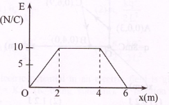
1. 30V
2. 60V
3. 40V
4. 80V
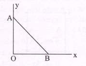
As per this diagram a point charge +q is placed at the origin O. Work done in taking another point charge −Q from the point A{co−ordinates (0, a)} to another point B{co-ordinates (a,0)} along the straight path AB is -
1.
2. zero
3.
4.
Three concentric spherical shells have radii a, b and c(a <b <c) and have surface charge densities σ,−σ and σ respectively. If , and denote the potentials of the three shells, then, for c=a+b, we have-
1. ==
2. =
3. =
4.
Four electric charges +q,+q,−q and −q are placed at the comers of a side 2L . (see figure). The electric potential at point A, midway between the two charges +q and +q, is
1. Zero
2.
3.
4.
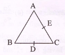
The charges, each +q, are placed at the corners of an isosceles triangle ABC of sides BC and AC,2a. D and E are the mid points of BC and CA. the work done in taking charge Q from D to E is -
1.
2.
3.
4. Zero
In a region the potential is represented by V(x,y,z)=6x−8xy−8y+6yz, where V is in
volts and x,y,z are in meters. The electric force experienced by a charge of 2 coulomb situated at point (1,1,1) is -
1. 6N
2. 30N
3. 24N
4. 4N
Two identical charged spheres suspended from a common point by two massless strings of length l, are initially at a distance d (d << l) apart because of their mutual repulsion. The charges begin to leak from both the spheres at a constant rate. As a result, the spheres approach each other with a velocity v. Then v varies as a function of the distance x between the spheres, as:
1.
2.
3.
4.
Two identical thin rings, each of radius R meters, are coaxially placed at a distance R meters apart. If coulomb and coulomb uniformly spread on the two rings, the work done in moving a charge q from the center of one ring to that of other is-
`1. Zero
2.
3.
4.
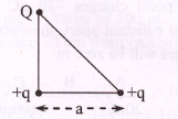
Three charges Q,+q and +q are placed at the vertices of a right-angle isosceles triangle as shown in figure. The net electrostatic energy of configuration is zero. Q is equal to-
1.
2.
3. −2q
4. +q
An elementary particle of mass m and charge e is projected with velocity v at a much more massive particle of charge Ze, where Z>0. What is the closest possible approach of the incident particle ?
1.
2.
3.
4.
64 small drops of mercury, each of radius 'r' and charge q are combined to form a big drop. The ratio of the surface density of the charge of each small drop to that of a big drop is-
1. 4:1
2. 1:4
3. 1:64
4. 64:1
Five identical plates each of area A are joined a shown in the figure. The distance between the plates is d. The plates are connected to a p.d. of V volts. The charge on plates 1 and 4 will be-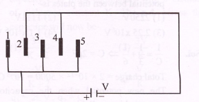
1.
2.
3.
4.
Calculate the reading of voltmeter between
X and Y then () is equal to -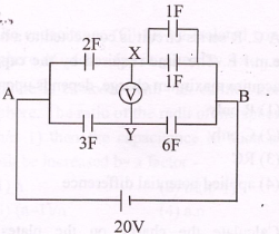
1. 10V
2. 13.33V
3. 3.33V
4. 10.33V
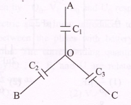
Three capacitors of capacitors are connected as shown in the figure. The points A, B andC are at potential V,V and V respectively. Then the potential at O will be −
1.
2.
3.
4. zero
A circuit has a section AB as shown in the fig. With E = 10V, =1.0μF, =2.0μF and the potential difference −=5V. The voltage across is-
1. zero
2. 5V
3. 10V
4. 15V
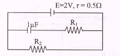
A 1μF capacitor is connected in the circuit shown below. The e.m.f of the cell is 2 volts and the internal resistance is 0.5 ohm. The resistors and have values of 4 ohms and 1 ohm respectively. The charge on the capacitor must be-
1. 2μC
2. 1μC
3. 1.33μC
4. zero
An infinite number of identical capacitors each of capacitance 1μF are connected as in
adjoining figure. Then the equivalent capacitance between A and B is-
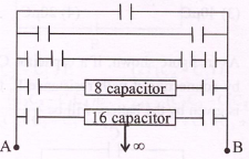
1. 1μF
2. 2μF
3. μF
4. ∞
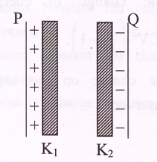
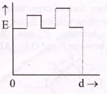
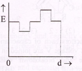
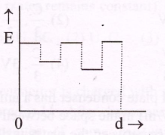
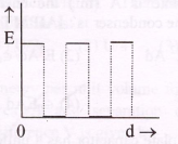
Two thin dielectric slabs of dielectric constants and (<) are inserted between plates of a parallel plate capacitor, as shown in the figure. The variation of electric field 'E' between the plates with distance 'd' as measured from plate P is correctly shown by :
1. 
2. 
3. 
4. 
A parallel plate air capacitor of capacitance C is connected to a cell of emf V and then
disconnected from it. A dielectric slab of dielectric constant K, which can just fill the air gap of the capacitor, is now inserted in it.
Which of the following is incorrect ?
1. The potential difference between the plates decreases K times
2. The energy stored in the capacitor decreases K time.
3. The change in energy stored is .
4. The charge on the capacitor is not conserved.
A parallel plate air capacitor has capacity ’C', distance of separation between plates is ’d′ and potential difference ′V′ is applied between the plates. Force of attraction between the plates of the parallel plate air capacitor is :
1.
2.
3.
4.
A capacitor of 2 is charged as shown in the diagram. When the switch S is turned to position 2, the percentage of its stored energy dissipated is: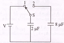
1. 20%
2. 75%
3. 80%
4. 0%
The effective capacitance between the points P and Q of the arrangement shown in the figure. is -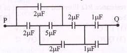
1. (1/2)
2. 1
3. 2
4. 1.33
When the key is pressed at time t = 0 then which of the following statement about the current i in the resistor AB of the given circuit is true - 
1. at t = 0, i = 2mA and with time it goes to 1mA
2. i oscillates between 1 mA and 2 mA
3. i = 2 mA at all t
4. i = 1 mA at all t
The combination of capacitors with =3μF, =4μF and =2μF is charged by connecting AB to a battery. Consider the following statements -
(I) Energy stored in = Energy stored in + Energy stored in
(II) Charge on = Charge on + Charge on
(III) Potential drop across = Potential drop across = Potential drop across
Which of these are correct −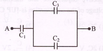
1. I and II
2. II only
3. I and III
4. III only
In an LCR circuit as shown below both switches are open initially. Now switch is closed kept open. (q is charge on the capacitor and =RC is Capacitive time constant). Which of the following statement is correct ?
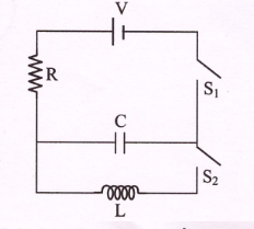
1. At t=2τ, q=CV(1−e)
2. At t=, q=CV(1−e)
3. Work done by the battery is half of the energy dissipated in the resistor
4. At t=τ, q=CV/2
A parallel plate capacitor having plates of area S and plate separation d, has apacitance in air. When two diclectrics of different relative permittivities (=2 and =4) are introduced between the two plates as shown in the figure, the capacitance becomes . The ratio is 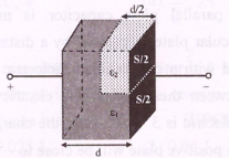
1. 6/5
2. 5/3
3. 7/5
4. 7/3
A combination of capacitors is set up as shown in the figure. The magnitude of the electric ficld, due to a point charge Q (having a charge equal to the sum of the charges on the 4μF and 9μF capacitors), at a point distant 30m from it, would equal -
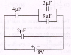
1. 240 N/C
2. 360 N/C
3. 420 N/C
4. 480 N/C